Injection Molding Machine Explained: Types, Components, Processes & Manufacturing Technology Insights
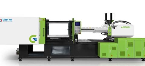
Injection molding machines are industrial systems used to manufacture components by injecting molten or flowable material into a specially designed mold. The material takes the shape of the mold cavity and solidifies or cures under controlled conditions before the finished part is removed.
Injection molding is widely associated with thermoplastics, but related processes can also use thermosetting materials, liquid silicone rubber, and other specialised materials. The machine configuration depends on the material, product geometry, production volume, and required quality.
Common applications include automotive components, electrical housings, packaging, household products, medical-device components, industrial parts, and consumer electronics enclosures. Some products are small and lightweight, while others require large machines capable of handling substantial molds and high clamping forces.
Modern injection molding systems combine mechanical assemblies, hydraulic or electric drives, temperature controls, programmable logic controllers, sensors, and automated handling equipment. Understanding these systems helps explain how manufacturers control part dimensions, surface finish, production consistency, and material usage.
What Is an Injection Molding Machine?
An injection molding machine is a manufacturing system that prepares material, injects it into a mold, applies the necessary clamping force, and controls the conditions required to form a finished component.
A conventional thermoplastic injection molding cycle includes several major stages:
Plastic pellets or granules enter the machine through a hopper.
A rotating screw conveys and melts the material inside a heated barrel.
The machine closes and clamps the mold.
Molten plastic is injected into the mold cavity.
Pressure is maintained to compensate for material shrinkage.
The material cools and solidifies.
The mold opens, and the component is ejected.
The exact sequence and processing conditions vary with the material, machine design, and part requirements. Thermosetting materials and liquid silicone rubber require different material preparation and curing approaches.
Importance of Injection Molding in Modern Manufacturing
Injection molding supports the production of components with complex shapes, repeatable dimensions, and detailed surface features.
1. High-Volume Production
Once the process is properly developed, injection molding can produce large quantities of components through repeated cycles.
Production capacity depends on cycle time, mold cavities, machine performance, material behaviour, and the time needed for handling and inspection.
2. Consistent Component Geometry
A properly designed mold and controlled process can produce parts with repeatable shapes and dimensions.
Consistency requires suitable mold design, machine settings, material quality, maintenance, and inspection.
3. Complex Product Design
Injection molding can create features such as ribs, bosses, clips, channels, textured surfaces, and integrated fastening elements.
Design limitations still apply. Wall thickness, draft angles, material flow, cooling, and ejection must be considered during product development.
4. Material Efficiency
The process can use material efficiently when the part, runner system, and process are designed appropriately.
However, sprues, runners, rejected components, purging material, and process instability can generate waste. Some thermoplastic scrap may be recoverable where material properties, contamination controls, and product specifications permit.
5. Repeatable Manufacturing
Automated machine settings and controlled production cycles can reduce variation between parts.
Repeatability depends on process validation, material consistency, equipment condition, and effective quality management.
6. Product Integration
Some components can combine several design features into a single molded part. This may reduce the number of separate components or assembly steps required.
The suitability of this approach depends on mechanical loads, material properties, product design, and manufacturing requirements.
Major Types of Injection Molding Machines
Injection molding machines are commonly classified according to their drive system, clamping arrangement, or specialised material-processing function.
1. Hydraulic Injection Molding Machines
Hydraulic machines use pressurised hydraulic fluid to operate the injection unit, clamping mechanism, or other movements.
A hydraulic pump supplies pressure, and valves direct fluid to the relevant actuators.
Common characteristics include:
Hydraulic cylinders for selected machine movements
High force capability
Adjustable movement and pressure settings
Suitability for many general-purpose applications
Hydraulic oil and filtration maintenance requirements
Hydraulic machines remain widely used in industrial manufacturing. Their energy consumption and temperature management depend on pump design, operating conditions, and whether the system uses fixed-speed, variable-displacement, or servo-controlled technology.
2. All-Electric Injection Molding Machines
All-electric machines use electric servo motors and mechanical transmission systems to operate the injection, clamping, metering, and other machine movements.
Potential advantages include precise motion control, repeatable positioning, and reduced dependence on hydraulic oil for the main machine movements.
Typical characteristics include:
Servo-driven axes
Programmable movement profiles
Precise screw and clamping control
Reduced hydraulic-system maintenance
Potential energy savings in suitable applications
Performance varies by machine design and production conditions. All-electric systems still require maintenance of their motors, drives, lubrication points, and mechanical assemblies.
3. Hybrid Injection Molding Machines
Hybrid machines combine electric and hydraulic technologies.
For example, electric servo drives may control screw rotation or injection movement, while a hydraulic system provides clamping or other high-force operations.
The objective is to combine selected advantages of both technologies. The actual performance depends on the configuration, application, and control strategy.
4. Horizontal Injection Molding Machines
Horizontal machines have a mold arrangement in which the mold opens and closes along a horizontal axis.
They are commonly used for general-purpose plastic components, packaging products, housings, and many automotive parts.
Their layout can support automated part removal and conveyor-based handling. Available floor space, mold access, and the intended automation arrangement influence installation planning.
5. Vertical Injection Molding Machines
Vertical machines arrange the clamping and mold system along a vertical axis.
Some configurations are suitable for insert molding, where metal or another component is placed into the mold before plastic is injected around it.
Applications may include electrical connectors, threaded inserts, selected industrial components, and specialised assemblies.
The suitability of a vertical machine depends on mold design, insert-handling requirements, operator access, and the production method.
6. Multi-Component Injection Molding Machines
Multi-component systems can inject two or more materials or colours into a single product during a coordinated molding process.
Depending on the machine and mold, the process may use multiple injection units, rotating mold sections, transfer mechanisms, or other specialised arrangements.
Applications include dual-colour buttons, soft-touch handles, seals, and components that combine materials with different properties.
Material compatibility, bonding, shrinkage, and process sequencing must be considered during development.
7. Micro-Injection Molding Machines
Micro-injection molding systems are designed for very small or highly detailed plastic components.
These systems require precise control of material dosing, injection, mold temperature, and cavity filling.
Applications may include miniature connectors, specialised medical components, precision instruments, and small technical parts.
Part quality can be particularly sensitive to material variation, mold accuracy, contamination, and process stability.
8. Specialised Injection Molding Systems
Some machines are designed for particular material families or production methods.
Examples include:
Liquid silicone rubber molding systems
Thermoset injection molding machines
Gas-assisted injection molding systems
Foam injection molding systems
Powder injection molding systems for suitable feedstocks
These processes differ in material preparation, injection behaviour, curing or solidification, and post-processing requirements. They should not be treated as interchangeable with conventional thermoplastic injection molding.
Main Components of an Injection Molding Machine
An injection molding machine contains several coordinated assemblies. Each performs a specific role in preparing the material, filling the mold, controlling the process, and removing the finished component.
1. Hopper
The hopper stores and feeds raw material into the machine's barrel.
It may include a drying or material-handling connection where required. Some materials, including certain engineering plastics, need controlled drying before processing to prevent moisture-related defects.
Material handling should protect pellets from contamination and moisture where relevant.
2. Feed Throat
The feed throat connects the hopper to the barrel and allows material to enter the screw channel.
Temperature control around this area can help prevent premature softening or inconsistent feeding.
3. Barrel
The barrel houses the rotating and reciprocating screw. Heating bands or other temperature-control systems help bring the material to the required processing condition.
The barrel must withstand the mechanical loads, temperatures, and material exposure associated with the intended application.
4. Reciprocating Screw
The screw is one of the most important components in a conventional thermoplastic injection unit.
Its functions include conveying material, melting and mixing it, and preparing a measured shot for injection.
A typical screw has three functional regions:
Feed zone: conveys solid pellets forward.
Compression or transition zone: compresses and melts the material.
Metering zone: helps establish a consistent melt condition and prepares material for injection.
The screw geometry should match the polymer and application. Different screw designs may be needed for materials with different melting, mixing, or shear characteristics.
5. Nozzle
The nozzle connects the heated barrel to the mold's sprue bushing.
It provides a controlled path for molten material to enter the mold. Nozzle design, temperature, and contact with the mold influence material flow and sealing.
An unsuitable nozzle setup can contribute to leakage, drooling, or inconsistent filling.
6. Injection Drive
The injection drive moves the screw forward to push molten material into the mold.
Depending on the machine, this may use hydraulic cylinders, electric servo systems, or a hybrid arrangement.
The drive must provide the required speed, pressure, and repeatability for the selected material and part geometry.
7. Clamping Unit
The clamping unit holds the mold halves together during injection and packing.
It must resist the force created by the pressure of material inside the mold cavity.
Clamping systems may use toggle mechanisms, direct hydraulic clamping, or other arrangements.
8. Mold
The mold contains the cavities and channels that define the component's shape.
It commonly includes two main halves mounted on the moving and stationary platens. Depending on its design, it may also contain cores, slides, lifters, inserts, cooling channels, vents, and ejection mechanisms.
Mold design strongly influences part geometry, cooling time, surface quality, and the likelihood of defects.
9. Platens and Tie Bars
Platens support the mold halves. Tie bars guide and support the clamping system in many machine designs.
Their dimensions and structural characteristics influence the maximum mold size, clamping capacity, and available mold installation space.
10. Ejection System
The ejection system removes the solidified component from the mold.
It may use ejector pins, plates, sleeves, air assistance, or other mechanisms.
Ejection must be designed to release the part without causing excessive deformation, surface damage, or stress.
11. Temperature-Control System
Temperature-control equipment manages the barrel, nozzle, mold, and, where required, other process components.
Depending on the application, it may include heaters, thermocouples, water circuits, oil circuits, or dedicated temperature-control units.
Stable temperature management is important because material viscosity, filling behaviour, cooling, and dimensional stability depend on thermal conditions.
12. Control Panel and Sensors
The control system allows operators to set and monitor machine parameters.
Sensors may measure temperature, pressure, position, screw rotation, or other operating variables.
Modern systems can record process data and display alarms, helping operators identify deviations and maintain documented production settings.
The Injection Molding Process Explained
A conventional thermoplastic injection molding cycle includes several stages. These stages are closely linked, and changes in one stage can influence the quality of the finished component.
Stage 1: Material Preparation
Plastic pellets or granules are selected according to the product specification.
Some polymers require drying before processing. Recycled material, colourants, and additives must be controlled so that the resulting material meets the required properties.
Stage 2: Plasticisation
The screw rotates and conveys the pellets through the heated barrel.
Heat from the barrel and energy generated by mechanical shear help melt and mix the material.
The screw moves backward as the required shot accumulates in front of it.
Stage 3: Mold Closing and Clamping
The machine closes the mold and applies sufficient clamping force.
The mold must remain closed during filling and packing to prevent excessive parting-line opening and unwanted material leakage.
Stage 4: Injection
The screw moves forward, pushing molten material through the nozzle and runner system into the mold cavity.
Injection speed and pressure must be suitable for the material, cavity geometry, wall thickness, and venting arrangement.
Stage 5: Packing and Holding
After the cavity is substantially filled, the machine may maintain pressure for a defined period.
This helps compensate for material shrinkage as the part cools. The appropriate holding pressure and time depend on the polymer, gate design, and part geometry.
Stage 6: Cooling
The material cools inside the mold until it has sufficient rigidity for ejection.
Cooling channels remove heat from the mold. Cooling time depends on wall thickness, material properties, mold temperature, and cooling-system performance.
Stage 7: Mold Opening
The clamping unit separates the mold halves after the required cooling stage.
The opening movement must provide enough clearance for the component and ejection system.
Stage 8: Part Ejection
The ejection system releases the molded component from the mold.
The part may then be transferred by an operator or automated handling system for inspection, trimming, assembly, or further processing.
Stage 9: Cycle Restart
The machine prepares for the next cycle. In many conventional systems, screw recovery and material preparation overlap with cooling, helping reduce overall cycle time.
The complete cycle is repeated according to the production schedule and required quality controls.
Important Injection Molding Parameters
Injection molding relies on coordinated control of material and machine conditions.
| Parameter | Function | Potential effect when poorly controlled |
|---|---|---|
| Barrel temperature | Helps melt and condition the material | Incomplete melting, degradation, or unstable flow |
| Mold temperature | Influences cooling, surface finish, and crystallisation in relevant polymers | Warpage, surface defects, or dimensional variation |
| Injection speed | Controls how quickly the cavity fills | Short shots, flow marks, or other filling defects |
| Injection pressure | Provides force to move material into the cavity | Incomplete filling or excessive stress |
| Holding pressure | Compensates for shrinkage before gate freeze | Sink marks, voids, or dimensional variation |
| Cooling time | Allows the part to solidify sufficiently | Deformation, sticking, or unnecessarily long cycles |
| Screw speed | Influences material preparation and shear | Inconsistent melting or excessive material heating |
| Clamping force | Keeps mold halves closed during injection | Flash if insufficient; unnecessary machine load if excessive |
| Shot size | Determines the quantity of material prepared for each cycle | Inconsistent filling or excessive material residence |
These parameters interact with one another. Adjustments should be made systematically and according to the material supplier's guidance, machine limits, mold requirements, and validated process conditions.
Materials Used in Injection Molding
Material selection affects strength, flexibility, temperature resistance, appearance, chemical compatibility, and processing behaviour.
1. Polypropylene (PP)
Polypropylene is used in many household products, packaging components, automotive parts, and general-purpose molded items.
It has a relatively low density and can provide useful chemical resistance. Its shrinkage and stiffness characteristics should be considered during mold design.
2. Polyethylene (PE)
Selected polyethylene grades are used for caps, containers, closures, and other molded components.
Material behaviour varies by grade, including density, stiffness, flow characteristics, and shrinkage.
3. Acrylonitrile Butadiene Styrene (ABS)
ABS is commonly used for housings, enclosures, and selected consumer or industrial components.
It can provide a combination of impact resistance and surface finish, although the appropriate grade depends on the product's mechanical and environmental requirements.
4. Polycarbonate (PC)
Polycarbonate is used for selected transparent or impact-resistant components, including protective covers and technical parts.
Processing conditions must account for moisture sensitivity, temperature requirements, and the intended mechanical and optical properties.
5. Polyamide (Nylon)
Polyamide materials are used in gears, connectors, mechanical components, and other applications requiring selected strength and wear characteristics.
Many grades are moisture-sensitive, so material conditioning and moisture control can be important.
6. Polystyrene (PS)
Polystyrene is used for selected rigid molded components, housings, and other applications where its properties are suitable.
The choice between general-purpose and impact-modified grades depends on the required toughness and appearance.
7. Thermoplastic Elastomers
Thermoplastic elastomers combine selected elastic characteristics with thermoplastic processing behaviour.
They may be used for grips, seals, flexible components, and soft-touch features. Compatibility with the other molded material is important in multi-component applications.
8. Engineering and Speciality Materials
Other materials may include PBT, PET, POM, PPS, liquid silicone rubber, and specialised filled or reinforced compounds.
These materials can require particular drying, temperature, venting, screw, mold, or curing arrangements. The material supplier's processing guidance should be followed.
Mold Design and Its Role in Product Quality
The mold is a major determinant of the final component's geometry and quality.
Cavity and Core Design
The cavity defines the external shape, while cores form internal spaces and selected features.
The design must account for the component's geometry, material flow, cooling, ejection, and expected shrinkage.
Gate and Runner System
The runner system carries material from the machine nozzle to the cavity. The gate controls the entry point and flow into the part.
Gate location and size can affect filling patterns, weld lines, packing, surface appearance, and material waste.
Venting
Air and gases inside the mold must escape as the cavity fills.
Insufficient venting can contribute to burn marks, incomplete filling, or other defects. Vent design must be appropriate for the material and process.
Cooling Channels
Cooling channels remove heat from the mold.
Their layout influences cooling uniformity, cycle time, and dimensional stability. Poorly balanced cooling may contribute to warpage or uneven shrinkage.
Draft Angles and Ejection
Draft angles help the part release from the mold. Ejector pins and related mechanisms must be positioned to avoid unacceptable marks or deformation.
Mold Maintenance
Molds require cleaning, inspection, lubrication where specified, and repair of worn components.
Damaged cavities, blocked cooling channels, worn slides, or degraded vents can affect part quality and production stability.
Common Injection Molding Defects and Their Causes
Injection molding defects may result from material behaviour, machine settings, mold design, or equipment condition.
Short Shots
A short shot occurs when the mold cavity is not completely filled.
Possible causes include insufficient material, unsuitable injection conditions, restricted flow, poor venting, or an unsuitable gate design.
Improvement: Review shot size, material preparation, filling conditions, venting, and the mold's flow path.
Flash
Flash is a thin layer of unwanted material that escapes between mold surfaces or through a gap.
Possible causes include insufficient clamping force, damaged parting surfaces, excessive cavity pressure, or incorrect mold alignment.
Improvement: Inspect the mold, verify process settings, and confirm that the clamping system is operating within the intended conditions.
Sink Marks
Sink marks are local surface depressions caused by uneven shrinkage, often in thicker regions.
Improvement: Review part geometry, holding pressure, packing time, gate design, and cooling conditions.
Warpage
Warpage occurs when a part deforms after molding because of uneven shrinkage or residual stresses.
Improvement: Examine cooling balance, wall thickness, material behaviour, mold design, and ejection timing.
Weld Lines
Weld lines can form where separate material flow fronts meet.
Their visibility and strength depend on material characteristics, flow conditions, geometry, and temperature.
Improvement: Review gate locations, filling patterns, material condition, and process parameters.
Burn Marks
Burn marks may result from trapped gas, excessive local heating, or material degradation.
Improvement: Check mold venting, filling speed, material residence time, and temperature settings.
Bubbles and Voids
Voids or bubbles can result from trapped gas, moisture, or shrinkage during solidification.
Improvement: Investigate material drying, packing conditions, venting, and the geometry of thicker sections.
Surface Flow Marks
Flow marks may appear when material does not fill the cavity uniformly.
Improvement: Review material temperature, mold temperature, injection speed, and gate design in a controlled troubleshooting process.
Corrective action should be based on inspection and process evidence rather than changing several machine settings at once.
Automation in Injection Molding
Automation can connect the molding machine with part handling, inspection, material delivery, and downstream manufacturing operations.
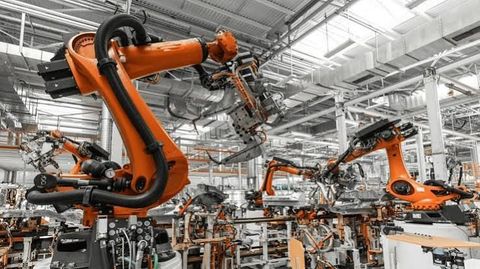
Robotic Part Removal
Robots can remove molded components from the mold and transfer them to a conveyor, inspection station, or assembly area.
The robot must be coordinated with the machine's cycle and safety interlocks.
Automatic Material Handling
Material-handling systems can convey pellets from storage to the machine and may include dryers, loaders, blenders, and controlled dosing equipment.
Suitable material identification and contamination prevention are important when several polymers or colours are used.
In-Mold and Post-Mold Inspection
Sensors and vision systems may check selected dimensions, visual features, or the presence of required components.
Automated inspection can improve monitoring, but its effectiveness depends on the inspection method, detection limits, and validation.
Automated Packaging and Assembly
Molded parts can be transferred to automated assembly stations, marking systems, or packaging equipment.
Integration requires coordination of cycle times, part orientation, traceability, and handling requirements.
Production Data Collection
Machine controls may record cycle times, temperatures, pressures, alarms, and production counts.
These records can support process analysis, quality investigations, and maintenance planning.
Smart Manufacturing and Industry 4.0
Industry 4.0 refers to the use of connected equipment, automation, data systems, and analytical technologies to improve manufacturing visibility and coordination.
Programmable Logic Controllers
Programmable logic controllers manage defined machine operations and coordinate signals from sensors, actuators, and safety systems.
Human-Machine Interfaces
Human-machine interfaces allow operators to view settings, monitor operating status, respond to alarms, and select permitted machine functions.
Supervisory Monitoring
Supervisory systems can collect information from multiple machines and present production status, cycle data, alarms, or other defined measurements.
Predictive Maintenance
Equipment data can be used to identify patterns associated with wear or developing faults.
Predictive maintenance is not a guarantee of failure prevention. Its effectiveness depends on data quality, appropriate analysis, and follow-up by qualified maintenance personnel.
Digital Quality Records
Connected production records can link machine settings, material batches, inspection results, and component identifiers.
This information can support traceability and investigations when a quality issue arises.
Artificial Intelligence in Process Monitoring
AI-based systems may analyse historical and live production data to identify unusual patterns or help predict selected quality outcomes.
These systems require validation, appropriate data governance, and human oversight. Their recommendations should not be treated as automatically correct.
Energy Efficiency and Sustainable Manufacturing
Injection molding involves energy use for material melting, injection, mold clamping, cooling, and auxiliary equipment.
Servo-Driven Systems
Servo-driven hydraulic and all-electric systems can adjust energy use according to operating demands. Actual savings depend on machine design, material, cycle, and production conditions.
Efficient Heating
Appropriate barrel insulation and well-maintained temperature controls can reduce unnecessary heat loss.
Cooling-System Optimisation
Efficient mold cooling and correctly managed temperature-control equipment can support stable production and reduce unnecessary energy use.
Material Waste Reduction
Stable process control, suitable mold design, and careful handling can reduce rejected parts and purging waste.
Regrinding and reusing scrap should only be carried out where the material specification, contamination controls, and product requirements permit it.
Equipment Life Extension
Preventive maintenance, component repair, and appropriate machine operation can extend useful equipment life and reduce avoidable replacement.
Sustainability decisions should consider energy, materials, water, waste, product performance, and equipment lifespan together.
How to Select an Injection Molding Machine
Machine selection should begin with the product and production requirements rather than a single machine specification.
1. Define the Product
Determine the component's dimensions, geometry, wall thickness, material, surface requirements, and expected mechanical performance.
2. Estimate Production Volume
Establish the required output, operating schedule, number of cavities, and acceptable cycle time.
Production planning should include changeovers, maintenance, inspection, and expected downtime.
3. Calculate Clamping Requirements
Clamping force depends on factors such as projected part area, cavity pressure, material behaviour, and mold design.
The required force should be calculated by qualified process or mold engineers. A larger clamping rating is not automatically better for every application.
4. Assess Shot Capacity
The injection unit must accommodate the required shot size within the manufacturer's recommended operating range.
Shot size should be evaluated in relation to the material, mold, and machine specification.
5. Check Mold Dimensions
Confirm the available platen dimensions, tie-bar spacing where applicable, mold thickness range, opening stroke, and ejection requirements.
6. Choose a Drive System
Compare hydraulic, electric, and hybrid designs according to precision, energy use, cycle requirements, maintenance capabilities, and application needs.
7. Review Material Compatibility
Confirm that the screw, barrel, nozzle, temperature-control range, and other components are suitable for the intended polymer or specialised material.
8. Plan Automation
Determine whether the process requires robotic removal, insert loading, automated inspection, material drying, conveyors, or downstream assembly.
9. Evaluate Safety and Maintenance
Review guarding, emergency stops, interlocks, electrical protection, technical documentation, spare-part support, and maintenance access.
10. Validate the Process
Where appropriate, conduct molding trials with the intended material and mold. Confirm that the process can meet the required dimensions, appearance, mechanical properties, and production targets.
Applications of Injection Molding Machines
Injection molding is used across a broad range of manufacturing sectors.
| Industry | Typical components | Main considerations |
|---|---|---|
| Automotive | Clips, housings, interior trim | Temperature resistance, durability, dimensional control |
| Electronics | Enclosures, connectors, insulating components | Electrical properties, precision, heat management |
| Packaging | Caps, closures, containers | Cycle time, weight consistency, material selection |
| Healthcare | Selected housings and medical-device components | Traceability, material requirements, validated manufacturing |
| Household products | Storage items, handles, kitchen components | Durability, surface finish, practical design |
| Industrial equipment | Gears, brackets, protective covers | Mechanical properties, wear, dimensional accuracy |
| Construction | Selected fittings, clips, and connectors | Strength, environmental exposure, long-term performance |
| Consumer products | Buttons, casings, accessories | Appearance, repeatability, material choice |
The required process controls depend on the component and its intended use. Regulated or safety-critical products may require additional documentation, testing, and process validation.
Injection Molding Regulations and Standards in India
Injection molding operations in India may need to comply with requirements relating to worker safety, environmental management, electrical equipment, product specifications, and material use.
The applicable requirements depend on the industry, facility, polymer, component, and intended market.
Factory and Occupational Safety Requirements
Manufacturing facilities should identify the workplace safety legislation and rules applicable to their operations. Important subjects include machine guarding, operator training, electrical safety, hazardous energy isolation, and emergency procedures.
The current framework and applicable state requirements should be verified through official government sources.
Bureau of Indian Standards
The Bureau of Indian Standards publishes standards relevant to plastics, materials, testing, and selected finished products.
A particular standard or certification may be voluntary or mandatory depending on the product and applicable regulation. Current requirements can be checked through the Bureau of Indian Standards.
Environmental Requirements
Manufacturing facilities may be subject to requirements covering waste management, emissions, pollution control, and the handling of industrial materials.
Applicable permissions and obligations should be confirmed with the relevant central or state pollution-control authority.
Plastic Waste and Extended Producer Responsibility
India has rules addressing plastic waste management and extended producer responsibility for specified entities and activities.
The applicability depends on the role of the organisation, the products and packaging involved, and current regulatory provisions. Official information is available through the Central Pollution Control Board.
Product-Specific Requirements
Components intended for healthcare, food contact, electrical applications, or other regulated uses may need to meet additional requirements.
Manufacturers should verify the applicable standards and legal obligations before defining the production process.
Regulations and standards can change. Facilities should consult current official sources and qualified compliance professionals rather than relying solely on general summaries.
Frequently Asked Questions
1. What is an injection molding machine used for?
An injection molding machine forms components by injecting material into a mold under controlled conditions. It is commonly used to manufacture plastic housings, packaging components, automotive parts, connectors, and household products.
2. What are the main types of injection molding machines?
Common types include hydraulic, all-electric, hybrid, horizontal, vertical, multi-component, and micro-injection molding machines. Specialised systems also exist for materials such as liquid silicone rubber and thermosetting compounds.
3. What is the function of the screw in an injection molding machine?
In conventional thermoplastic injection molding, the screw conveys pellets, helps melt and mix the material, prepares the required shot, and moves forward to inject the melt into the mold.
4. What is clamping force?
Clamping force is the force that holds the mold halves together during injection and packing. It must be appropriate for the projected area of the molded part, cavity pressure, and mold design.
5. What is the difference between hydraulic and electric injection molding machines?
Hydraulic machines use pressurised fluid to power selected movements, while all-electric machines use electric motors and mechanical transmission systems. Hybrid machines combine both approaches. Performance depends on the application and specific machine design.
6. Why is mold temperature important?
Mold temperature affects how the material flows, cools, shrinks, and develops its surface characteristics. Incorrect conditions can contribute to dimensional variation, warpage, or surface defects.
7. What causes flash in injection molding?
Flash is unwanted thin material that escapes between mold surfaces or through a gap. Potential causes include insufficient clamping force, mold damage, misalignment, or excessive cavity pressure.
8. How does automation improve injection molding?
Automation can support material delivery, part removal, inspection, packaging, and production data collection. Its effectiveness depends on safe integration, reliable controls, appropriate programming, and maintenance.
Conclusion
Injection molding machines are important manufacturing systems for producing repeatable components with complex geometries and controlled dimensions. Their operation depends on coordinated material preparation, injection, clamping, cooling, and ejection.
Hydraulic, electric, hybrid, vertical, horizontal, and specialised machines provide different capabilities for different production requirements. Components such as the screw, barrel, nozzle, clamping unit, mold, ejection system, and control panel each contribute to the overall process.
Modern manufacturing increasingly combines injection molding with robotics, sensors, automated inspection, and connected production records. These technologies can improve process visibility and repeatability when supported by sound engineering, suitable materials, effective maintenance, and quality control.
Selecting the right machine requires careful assessment of product design, material characteristics, production volume, mold requirements, safety, and applicable regulations. A well-designed and validated process helps manufacturers produce consistent components while managing material use, equipment performance, and operational risks.
Disclaimer
This article is intended solely for general educational and informational purposes. It does not promote any particular injection molding machine brand, manufacturer, or commercial offering. Machine specifications, processing technologies, and regulatory requirements may change. Readers should verify current information through authoritative technical sources, equipment documentation, material suppliers, and qualified manufacturing professionals before making engineering, production, or compliance decisions.